Digital X-ray image processing system
Currently, the radiology applied several types of digital systems, this:
– CR system (Computed Radiography);
– CCD sensor (Socrates. from English. CCD, «Charge-Coupled Device») or PSA modules (Photo-diode Sensors Array/ Multi-CCD Detector Method);
– DR Detectors (Socrates. from English. DR, «Digital Radiography»);
Each of these systems and technologies has its own advantages and disadvantages. Let us examine them in detail.
I.
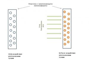
Work CR System (Computed Radiography) based on fixing the spatial X-ray image – memories phosphors. The receiver is a flexible image plate, coated with a phosphor stimulated luminescence, capable of storing the absorbed energy of the incident X-ray radiation in the quasi-stable state, and emit this energy as photons upon irradiation with visible light or infrared. The phosphor should have a high x-ray absorption coefficient, as well as a large light output per unit of energy absorbed.
For fast image pickup time constant of the phosphor must be less 10mks. Good to meet these requirements, barium fluoride, activated with europium, which is the basis for a commercially produced receivers forced luminescence.
Screen (plate), storage phosphor coated, It looks like a regular intensifying screen. The latent image on the screen that is able to be saved, depending on the type of phosphor, from several minutes to several days, before its quality drops below an acceptable level. This latent image can be read from the screen scanning system and reproduced CRT.
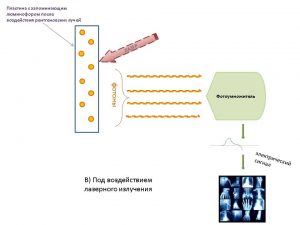
Reading the latent image produced by an infrared laser, which stimulates the phosphor, and it gives the stored energy in the form of visible light. This phenomenon is called photostimulated luminescence. She is, as glow conventional intensifying screens, proportional to the number of X-ray photons, absorbed the storage phosphor.
In the process of reading is not the whole screen is released the stored energy. To clear a phosphor screen of latent image, it is subjected to short-term processor intensive irradiation with visible light, then you can use the screen again.
The process of image reading is performed with a scanning laser, luminous flux scans the surface of the screen in raster sequence, like the electron beam television picture tube. The laser beam has a spot size approximately 0,1 mm, so the resolution of the image reaches 5-10 cells / mm. A phosphor excited by the laser light from each point on the screen is focused and converted into an electric signal by using a special optical system and the photomultiplier. Front of the photomultiplier is a filter, weakening the stimulated light, since its intensity is several orders of magnitude higher, than the light, emitted by a conventional intensifying screen.
photomultiplier, with a wide dynamic range, ranging converts the intensity of the light flux from the screen in varying electrical signal, which increases, measured and passes through the analog-to-digital converter, to form binary (digital) matrix, reflecting the brightness of each pixel indices. 12-bit system presents these indicators in the range 0 to 4095 (2№I = 4096). signal, translated into digital form, It is transmitted to the processor (buffer) Images. lookup table processor provides image transformation memory contents to the desired brightness and contrast range.
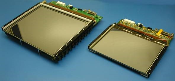
The main link, usually associated with X-ray machines CR complex, They are the standard type of X-ray cassettes, phosphorus containing special reusable plates. A workflow is as follows: made in a conventional manner after the patient image on a tape, the latter is placed in the digitizer, where the cassette is automatically withdrawn or read the plate, the image is transferred to digital form and sent to the workstation computer processing, then digitizer sensed image is erased from the plate, and the cassette is ready for the next shot.
II.
CCD Jobs (AAS) (Socrates. from English. CCD, «Charge-Coupled Device») or PSA module (Photo-diode Sensors Array/ Multi-CCD Detector Method).
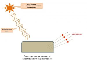
The principle of all devices with charging communication (AAS) based on the photoelectric effect - substance emitting electrons under the influence of electromagnetic radiation (visible light, infrared, ultraviolet, X-rays and other types of electromagnetic waves). electrons, emitted from a substance in the external photoeffect, called photoelectrons, and the electric current, formed by them in the ordered motion in the electric field, It called photocurrent.
CCD (CCD) -specialized analog integrated circuit, consisting of photosensitive photodiodes, Made silicon, Use the machine technology with a charge-coupled (AAS). In the optical receiver block incoming X-ray intensifying screen are converted into visible light, which is also stored in the video sensors.
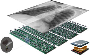
Each of the sensors handles a relatively small field of view to intensifying screen, which provides high-resolution images. The greater the number of sensors Video, set in the optical unit, the higher spatial resolution diagnostic images provided by the receiver. Image quality can be improved with the help of the scaling algorithms, selection of a region of interest, adjusting brightness and contrast, color inversion, etc.. Received image sensors is sent directly to the computer, processed and displayed on the monitor for a few seconds.
III.
The operating principle of DR detector (Socrates. from English. DR, «Digital Radiography»).
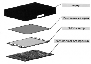
Currently, the production of flat-panel DR detector is developing two technologies: (Thin-film transistor) TFT and (Complementary metal–oxide–semiconductor) (CMOS).
TFT is based on a variety of field-effect transistor, in which both metallic contacts, and the semiconductor conduction channel is made in the form of thin films (from 1/10 to 1/100 microns).
CMOS manufacturing technology arrays of photosensitive field effect transistors with insulated gates and channels of different conduction.
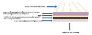
Comparative analysis of these technologies shows, that each of them has advantages and disadvantages. for example, TFT-photodetectors more radiation-and the technology easier to produce large-sized panels. In CMOS -fotopriemnikov less additive noise, they allow for high speed, which is especially important in interventional radiology. An important advantage of CMOS is the possibility of solar cells, the control circuit, amplifiers and analog-to-digital converter on the same chip. However, as a TFT, and CMOS panel fluoroscopy mode (at low doses per frame) have low signal / noise ratio due to additive noise. This greatly reduces the image quality. This disadvantage also have direct conversion panel. Therefore, to eliminate the influence on the image quality of additive noise, intensive research on electronic amplification (multiplication) image signal in semiconductors.
Mr
CONTROL
CONTROL 2